I2C Services
API 510, API 570, API 653, API 936 INSPECTIONS SERVICES
I2C offers comprehensive API inspection services to help your organization comply with regulatory, insurance and industry requirements. Our highly trained and professional staff is up to date on the latest standards and regulations ensuring a proactive approach to compliance.
I2C provides a wide range of inspection and data management services to ensure the integrity of your operating assets.
I2C‘s API inspection and testing services are performed in compliance with all API standards and recommended practices by certified 510, 570, and 653 inspectors. Our inspectors can provide support while your plant is in operation in addition to turnaround based inspection programs.
Minimum Qualification Requirements
- As outlined in the Appendix B of the API 510 Standards, the qualification requirements for API 510 applicants are based on the combination of education and experience related to pressure vessels. This experience must have been acquired within the last 10 years while employed by, or under contract with, an authorized inspection agency as defined in API 510.
- Based on the 10th edition of API-510, a National Board certification is no longer accepted as a substitution for passing the API-510 exam.
| Education | Minimum Years of Experience Required | Description of Experience Required |
| BS or higher in engineering or technology | 1 year | Supervision or performance of inspection activities as described in API 510. |
| 2-year degree or 2-year certificate in engineering or technology | 2 years | Design, construction, repair, operation, or inspection of pressure vessels, of which one year must be in supervision or performance of inspection activities as described in API 510. |
| High school diploma or equivalent | 3 years | Design, construction, repair, operation, or inspection of pressure vessels, of which one year must be in supervision or performance of inspection activities as described in API 510. |
| None | 5 or more years | Design, construction, repair, operation, or inspection of pressure vessels, of which one year must be in supervision or performance of inspection activities as described in API 510. |
Services Our Refractory Inspection Division Will Provide
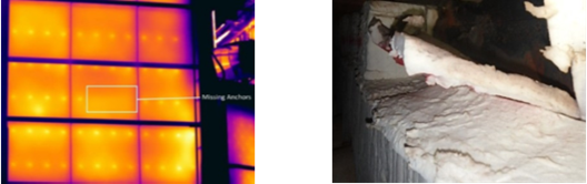
Using today’s best technology in thermal infrared imagery, the T1020 from FLIR, we are able to see refractory anchoring systems and potential issues while on-stream. This technology allows us to more accurately plan repairs during scheduled down time. I2C can follow your refractory installation from beginning stages in a fabrication shop to the plant when it goes online.
Services include:
- Pre-Turnaround Planning
- Consulting
- Turnaround Inspection
- Refractory Monitoring
- Refractory Lining Evaluations and Repair Recommendations
- Dry-out Monitoring
- Fabrication Shop Surveillance
- Emergency Shutdowns
Whether you have company specifications or would like to follow API-936, we will be the quality assurance and inspection partner you can count on to deliver top tier refractory inspection and consulting services.
Work ethic, family values, and the ability to meet client needs has led Industrial Inspection and Consulting to continue adding new products and services to our portfolio. Whether you are a current partner or new I2C client, the integrity, knowledge and wisdom our previous divisions are known for will also be present in our new refractory group.
To learn more about this service or others offered by
Industrial Inspection & Consulting,
contact us today.
Robert Nichols | Vice President Sales | 918.805.0074
I2C ANNOUNCES THE LATEST ADDITION TO THEIR PORTFOLIO, THE T1020 FROM FLIR
Industrial Inspection and Consulting is now working with the latest
technology in thermal infrared imagery, the T1020 from FLIR. This
introduction will allow I2C to provide their clients the ultimate tool in the industry, resulting in the sharpest images, and the truest temperatures.
Using infrared technology provides our clients immediate and accurate equipment conditions, resulting in greater accuracies and informed decisions.
Services and applications will include:
- Corrosion under insulation
- Detect safety hazards and costly failures before they happen
- Electrical Gear (motor control centers, breaker panels, fuses, connections etc.)
- Electrical inspections in refineries
- Heat exchangers
- HVAC systems, steam traps, water lines, radiant heat systems, power distribution (substations, transformers, transmission lines )
- Motors and Bearings, hydraulics systems, belts and pulley’s
- Piping process flow
- Refractory lining in piping, vessels, and process furnaces
- Refractory monitoring
- Restoration applications such as finding water leaks or damage
- Steam traps
- Tank aging and corrosion

Robert NicholsVice President Sales 918.805.0074
Brent MorrisonVice President Engineering 918.397.4601
To learn more about this service or others offered by
Industrial Inspection & Consulting, contact us today.
AWS-CWI WELD INSPECTION
I2C‘s team of certified welding inspectors (CWI) can pinpoint exactly what testing is necessary to qualify a weld, weld procedure, or individual welders. Each welding code follows three main categories of welding qualification; welding procedure specification (WPS), welding procedure qualification record (WPQR), and welder performance qualification (WPQ).
CORROSION ANALYSIS AND MITIGATION
Corrosion and corrosion mitigation are two of the most significant costs faced by industry, accounting for about $1.4 billion per year in the USA for the E&P sector, $1.7 billion for chemicals and $3.7 billion in refining and downstream.
Material selection and the influence of joining processes on material behavior are vital to cost effective construction and long-term operation of assets.
Process conditions and external environments need consideration in relation to environmentally assisted cracking, corrosion fatigue and corrosion failure modes for carbon steels and corrosion resistant alloys.
Integration of corrosion expertise with metallurgy, thermal spraying, NDE and fitness-for-purpose capabilities at I2C provides a service called upon for both failure investigation, asset integrity and R&D.
Development Of Inspection Plans
I2C has highly experienced and certified inspectors who are skilled in developing or updating inspection plans, creating or implementing corrosion monitoring programs, pre-turnaround and turnaround inspection plans. Our team regularly assists major players in the petrochemical industry with planning services utilizing Maximo, SAP, and others. Put our inspection team to work for you and realize potential cost savings through focused, well planned inspection and testing.
Failure Analysis
Material and equipment failures annually cost industry billions of dollars. The unfortunate loss and injury to life, the loss of production due to unscheduled work stoppages, the replacement costs, environmental damage and possible legal implications are just some of the repercussions of a failure. A metallurgical failure analysis is an essential step in decreasing the possibility of a recurrence of the same type of failure and helps minimize the associated costs.
Failure in an engineering sense, is a condition that prohibits a part to function, as intended. Failures often occur because a single or progressively applied load was greater than what the part could withstand or the environment was harsher than what material was designed or a combination of the two. The purpose of a failure analysis is to determine what caused the failure.
All failures leave evidence. Failure analysis is the process finding the evidence that indicates the specific cause of failure. Various tasks inspections, tests, and examinations are performed in order to collect the evidence, such as, but not limited to:
- Review of design parameters
- Visual examination
- Dimensional Inspection
- In-situ replication
- Nondestructive testing such as liquid penetrant examination, magnetic particle inspection, ultrasonic examination
- Stereomicroscopy
- Scanning electron microscopy
- X-ray diffraction
- Energy-dispersive X-ray spectroscopy
- Metallography
- Mechanical property testing such as tensile testing, bend tests, impact testing, hardness testing
- Chemical analysis
- Accelerated corrosion testing including testing for presence of microbiological contaminants
Test results alone do not constitute a failure analysis. It is not only the responsibility of a failure analyst to find evidence, but come to definitive conclusions as to the cause of failure. A thorough analysis should also include a discussion so that the reader understands all aspects of the findings and conclusions.
I2C’S APPROACH TO FAILURE ANALYSIS
I2C does not operate a laboratory. Testing technologies are constantly improving. It is difficult for any one commercial laboratory to always have the most up-to-date equipment and industry specific expertise. I2C failure analysts have working arrangement with numerous nationally recognized laboratories which gives us access to the latest equipment and appropriate expertise. This helps to control costs since I2C’s hourly rate for failure analysis/engineering is considerably less than rates charged by laboratories for their failure analysis. In addition to reduced engineering rates, by having numerous laboratories to choose from, I2C can select the one that offers the fastest turnaround time.
The field of metallurgy is enormous. There are literally thousands of engineering materials used in different industries and each metal and alloy group is susceptible to a variety of different failure modes specific to different service and operation conditions. These variables make it virtually impossible for any individual metallurgist or failure analyst to be an expert in them all. It just isn’t possible. This is why you should choose a failure analyst with not only the appropriate experiences and knowledge, but one that has access to a network of other experts.
Our direct experiences and associations with leading experts is your gateway to a successful resolution of your problem. I2C’s failure analysts have an average of 25 years of metallurgical and failure analysis experience in numerous industries, including oil and gas exploration, chemical, refining, transportation, nuclear, aerospace, avionic, and infrastructure. We have worked with leading experts in a variety of disciplines. If we do not know the answer, we know someone who does.
Not all of our clients are versed in metallurgy. We can be as technical as necessary; however, I2C believes that it is preferable that test results, conclusions, and discussion be presented in a well-written, well-formatted, and well-documented report that is easily understood by a non-metallurgist but yet still be useful in remedial action and be legally defensible.
Sometimes things go wrong. Failure analysis is the first step in making sure they do not go wrong again. Our experience and associations coupled with our realistic and pragmatic approach provide easily understood and definitive answers to difficult questions.
MATERIAL EVALUATION AND FAILURE ANALYSIS COMPLIMENT I2C’S MECHANICAL INTEGRITY INSPECTION PROGRAMS
Systems are routinely inspected to assure components are still within their design parameters and/or to monitor previously detected service-related deterioration. Periodic inspections include visual inspection, dimensional inspection, liquid penetrant examination, magnetic particle examination, ultrasonic testing, positive material identification and hardness testing. I2C performed these tests in accordance with applicable specifications by certified technicians. Results are reviewed and reported by mechanical and/or metallurgical engineers.
Deteriorated and/or failed components are often found during the periodic inspections which of course is why systems are inspected in the first place. Not only does I2C strongly recommend that analysis of failed components be performed to mitigate potential repercussions, we further recommend that specialized metallurgical testing be performed to evaluate areas of concern, particularly those that have been exposed high temperature/high pressure service since short and long term exposure to high temperatures, with or without pressure and/or stress, causes multiple types of damage that can lead to catastrophic failure. Some modes of high temperature failures are creep, thermal fatigue, flame impingement, embrittlement, carburization, decarburization, hydrogen damage, thermal shock, high temperature corrosion, and liquid metal embrittlement. Early detection of dangerous conditions that cannot be detected by visual examination alone can avoid catastrophic failures.
Although it is desirable, it is not always practical to cut samples from potentially damaged equipment for detailed laboratory examinations. Fortunately, I2C can nondestructively inspect exposed surfaces of the vessel/piping for possible high temperature damage by replication. Results can be provided almost immediately after testing/examination. Our portable digital microscope allows for real-time and in-depth microstructural analysis by our experienced metallurgists as opposed to traditional film replication that requires laboratory support.
I2C personnel are experienced in assessing materials exposed to higher than design temperatures. Assessments are performed in accordance with API 579, Part 11. I2C has the tools and experience to determine if any metallurgical or mechanical property changes have occurred, and if so how they affect the equipment’s expected service life.
Fire Damage Assessment or Heat Damage from Process Upset
When the worst happens, the I2C expert fire damage assessment team can help you inspect and identify the type and extent of the damage. We get you up and running again quickly, while reducing unnecessary replacements [1]. We are ready to rapidly deploy fire damage assessment teams to locations throughout the US and abroad when you need service fast!
Using field metallographic replication, ultrasonic testing, hardness testing, visual inspection, and other techniques, our fire damage analysts will assess the type and extent of the damage to every affected component. We then provide you with guidance or a fitness-for-service determination, and a plan to help you get back up and running quickly and safely. Here’s how it works:
An introduction to fire damage assessment of industrial components:
Typically, a customer will request our fire damage assessment, which usually includes a combination of visual inspection, portable Brinnell hardness evaluation, and field metallographic replication (FMR) of the components that have experienced fire damage. Customers should provide as much information as possible about the time, type, and nature of the fire, but often fires occur at unmanned facilities or during times when no personnel are present.
Fire damage assessment objectives include determination of the critical heat exposure zones, assessment of the condition of affected materials in the system, and repair or replacement recommendations for components, as needed. A report is provided with details of the results of inspection, evaluation, and the conclusions for repair or replacement. All told, we can help you save money by quickly returning to safe operations without replacing unncessary parts.
Fire Damage Assessment Methodology
Exposure to high-temperatures is not the only requirement for damage to occur in carbon steels and other components. In fact, steel piping, tubing, and pressure vessels are normally produced by pouring molten steel at temperatures above 2800 °F to make cast ingots. The casting process is normally followed by hot forming (e.g. hot rolling or forging) that is usually performed in the temperature range of 1800-2000 °F or above.
The next step of pipeline and pressure vessel fabrication usually includes welding, the process of depositing liquid steel on the carbon steel to bond the walls together. Welding is sometimes followed by post weld heat treatment (PWHT), involving heating at about 1150 °F or a similar specified temperature for several hours to achieve the desired strength and properties. A carbon steel vessel involved in a fire can experience thermal cycling during the fire event and with uncontrolled heating and cooling. The steel may reach temperatures similar to PWHT in areas and similar to normalizing (the process of heating to ≥1560 °F followed by air cooling, which reduces the strength of the steel) in other areas. Hence, the fact that steel is accidentally heated to these high temperatures does not necessarily mean that the steel is damaged.
It is on this basis that a fire damage assessment is conducted, leading to the determination of fitness for salvage for the vessel or recommendations for repair or replacement practices.
Fire Damage Assessment Procedures
The assessment procedures for evaluating pressure vessels, piping and tanks subjected to flame impingement and the radiant heat of a fire are covered by Part 11 of the API/ASME Standard on Fitness-For-Service API 579-1 / ASME FFS-13. These fire damage assessment procedures were applied in order to define the maximum heat exposure zone of the affected areas at the Operator’s Facility. The Level 1 assessment procedure of this part of the API/ASME standard is a screening criterion where the acceptability for continued service is based on the Heat Exposure Zones and the material of construction of the components affected during the fire.
The screening criteria are conservative, and calculations are not required to establish suitability for continued service. Components do not need a further assessment of mechanical properties if they are assigned to an acceptable Heat Exposure Zone and there is no mechanical damage or dimensional deviation. The Heat Exposure Zone levels for the materials of construction that are acceptable per a Level 1 assessment are shown in Table 1.
Table 1. Description of Heat Exposure Zones to Evaluate Fire Damage
| Heat Exposure Zone | Description |
| I | Ambient temperature during fire event, no fire exposure |
| II | Ambient to 65oC (150oF), smoke and water exposure |
| III | >65oC to 205oC (>150oF to 400oF), light heat exposure |
| IV | >205oC to 425oC (>400oF to 800oF), moderate heat exposure |
| V | >425oC to 730oC (>800oF to 1350oF), heavy heat exposure |
| VI | >730oC (>1350oF), severe heat exposure |
Note: The source for this material is API 579-1/ASME FFS-1. Details of the damage that is likely to occur in each zone are described in this document.
Visual Inspection
Visual examination of the piping, components and surrounding areas affected by the fire is normally conducted as the first step in the assessment. Visual inspection can provide a variety of tools for estimating the fire damage or temperature exposure in different zones and is the first step to determine the severity and extent of heat damage.
Hardness testing
To determine if the fire-exposed material suffered any softening or hardening due to microstructural degradation or changes during the fire (which would indicate a need for repair or replacement), hardness is usually measured with a portable hardness tester. To determine if fire-exposed material has suffered any softening or hardening due to microstructural degradation or changes during fire or process upset (which would indicate a need for repair or replacement), hardness is usually measured with a portable hardness tester. I2C inspectors often uses a tool commercially known as a “Telebrineller” hardness tester and a MIC 20 ultrasonic contact impedence hardness tester. The Telebrineller method measures “bulk” hardness of the sample by pushing into the material and measuring the amount of denting at a given pressure. The resulting measurement includes a volume measurement incorporating the surface and a depth of 2-3 mm below the surface. Telebrineller measurements can indicate fire damage that extends beyond the surface “skin” of the metal being tested. MIC 20 provides a expedient and precise reading, areas such as heat affected zones, and other small areas are readily tested. Application of either test method much be carefully chosen based on material type and desired result. I2C’s experienced staff has the knowledge to properly apply these techniques where applicable generally in conjunction with material assessment associated with elevated temperature exposure
Recommendations for Repair, Replacement, or Other Changes
Repairs to fire-damaged structures should provide the strength, fire resistance, durability and appearance appropriate to the proposed use and projected design life of the equipment. Fire-damaged structures are often capable of being repaired rather than replaced. Inspection experts can successfully assess fire-damaged structures using a range of forensic analysis techniques and specify well-informed repair solutions. As an alternative to demolition this can provide substantial savings in capital expenditure and also savings in consequential losses, by permitting earlier reuse and reoccupation of structures.
Finally, the results of the visual inspection, hardness testing, field metallographic replication, and other inspection efforts are analyzed using API specifications. recommendations for repair, replacement, or other changes to the materials are provided. In some cases, risk-based inspection (RBI), mechanical testing, or a mechanical integrity evaluation may be needed. I2C’s extensive network of vendors provides a unique benefit to clients by which mechanical testing is often completed in less than 24 hours.
The scope of work of fire damage assessment is typically:
- On site visit of the fire damage assessment team. We meet with the fire response team and perform a preliminary evaluation of the scope of the fire and associated damage.
- Interviews with personnel to determine the on-site conditions before and during the fire, along with possible cause of the failure.
- The heat exposure zones are identified based on API 579 FFS assessment guidelines. Visual inspection and NDE are often combined to complete the Level 1 FFS assessment.
- API 579 FFS Level 2 and Level 3 assessment is performed on anything which does not pass the Level 1 FFS inspection.
- Components may be shipped to labs or tested on-site by FMR and other means. A inspection and testing plan will be devised based on the assessment of Level 1 and Level 2 FFS.
- Level 3 FFS is performed with our mechanical analysis and FEA partners to determine if components are safe for continued operation.
Fitness For Service and Equipment Evaluation, Inspection and Reporting, up to Level 2
FFS is a well known and important concept in the oil & gas, chemical, petrochemical, and other process industries. Fitness for service is the ability to demonstrate the structural integrity of an in-service component even though it contains a flaw. It serves as a rational basis for defining flaw acceptance limits, and allows engineers to distinguish between benign and dangerous flaws.
FFS of any particular material is determined by performing a fitness for service assessment. Performing accurate FFS evaluations is an integral aspect of fixed equipment asset integrity management. On the other hand, failing to perform evaluations can lead to equipment failures which can further result in injury, loss of life, and severe financial and economic consequences.
These examinations are performed because even if a piece of equipment has a crack or other defect, this doesn’t necessarily mean that it’s unfit for service. Most equipment can continue in service despite small flaws, and to repair or replace equipment that can still be used would be an unnecessary and costly expense. Not only that, but unnecessary weld repairs can actually do more harm than good, as the quality of the new weld can often be less than the original one.
There are several ways to see if a flaw can cause a piece of equipment to be no longer fit for service. For cracks, fracture mechanics provides the mathematical framework for the examination by quantifying combinations of stress, flaw size, and fracture toughness.
While cracks tend to be the most dangerous, they’re not the only flaw that might warrant evaluation. Volumetric flaws such as corrosion pits, porosity, and slag may reduce the load-bearing capacity of a structure. Likewise, structural integrity may also be compromised by locally thinned areas which come grinding out cracks, thus FFS methodologies have been developed to evaluate local thinning. In these cases, acceptance criteria are based on limit load analyses rather than fracture mechanics models.
It is important to note though that FFS evaluation can’t provide an absolute delineation between safe and unsafe operating conditions. Uncertainties in input parameters such as stress, flaw size, and toughness often lead to a large uncertainty in the prediction of the critical conditions for failure. In general there are two ways to address this uncertainty. The more traditional approach has been to use conservative input values in a deterministic analysis. The result of such an analysis is a pessimistic prediction of critical flaw size or remaining life.
An alternative approach, one which is becoming more common, entails performing a probabilistic analysis that incorporates the uncertainties in the input data. The latter type of analysis does not result in an absolute yes/no answer as to whether or not a structure is safe for continued operation. Rather, a probabilistic analysis estimates the relative likelihood of failure, given all of the incorporated uncertainties. Probabilistic FFS analysis can be an integral part of a risk-based inspection (RBI) protocol, where inspection is prioritized according to the risk of significant injury or economic loss.
In Situ Hardness Testing, Near Non-Destructive
To determine if fire-exposed material has suffered any softening or hardening due to microstructural degradation or changes during fire or process upset (which would indicate a need for repair or replacement), hardness is usually measured with a portable hardness tester. I2C inspectors often uses a tool commercially known as a “Telebrineller” hardness tester and GE’s MIC 20 ultrasonic contact impedence hardness tester. The Telebrineller method measures “bulk” hardness of the sample by pushing into the material and measuring the amount of denting at a given pressure. The resulting measurement includes a volume measurement incorporating the surface and a depth of 2-3 mm below the surface. Telebrineller measurements can indicate fire damage that extends beyond the surface “skin” of the metal being tested. MIC 20 provides a expedient and precise reading, areas such as heat affected zones, and other small areas are readily tested with no noticeable damage to the part’s surface. Application of either test method must be carefully chosen based on material type and desired result. I2C’s experienced staff has the knowledge to properly apply these techniques where applicable generally in conjunction with material assessment associated with elevated temperature exposure.
Inspection Program Audits
Inspection of work areas and audits of safety programs are tools that can be used to identify problems and hazards before these conditions result in accidents or injuries. Audits also help to identify the effectiveness of safety program management and can be used as a guide to assure regulatory compliance and a safe workplace.
Responsibilities
Management
• Design and schedule audit and inspection procedures for all work areas, processes and procedures.
• Conduct routine audits and inspections
• Ensure audits are conducted by employees who understand the various safety programs and policies
Supervisors
• conduct informal daily safety inspections and ensure all unsafe conditions are corrected
• conduct documented weekly inspections and ensure all unsafe conditions are corrected
Corrections
All safety deficiencies found during audits and inspections should be corrected as soon as possible. Documentation of corrections should be made on the audit or inspection sheet. And conditions that present a hazards are to be corrected or controlled immediately.
Liquid or Dye Penetrant Testing
Dye penetrant testing is a non–destructive method for finding discontinuities that are open to the surface of solid and essentially non-porous materials. Indications of flaws can be found regardless of the configuration, internal structure, or chemical composition of work piece being tested and regardless of flaw orientation. Liquid penetrant can seep into (and be drawn into) various types of minute surface openings by capillary action. Because of this, the process is well suited for the detection of all types of surface cracks, laps, porosity, shrinkage areas, laminations and similar discontinuities in castings, forgings, welds and other product forms. Dye penetrant inspection is used extensively for the testing of wrought and cast products of ferrous and non-ferrous metals, powder metallurgy parts, ceramics and glass objects.
Magnetic Particle Inspection (MT)
MT is a non-destructive testing (NDT) process for detecting surface and slightly subsurface discontinuities in ferromagnetic materials such as iron, nickel, cobalt, and some of their alloys. The process puts a magnetic field into the part. The piece can be magnetized by direct or indirect magnetization. Direct magnetization occurs when the electric current is passed through the test object and a magnetic field is formed in the material. Indirect magnetization occurs when no electric current is passed through the test object, but a magnetic field is applied from an outside source. The magnetic lines of force are perpendicular to the direction of the electric current which may be either alternating current (AC) or some form of direct current (DC) (rectified AC).
The presence of a surface or subsurface discontinuity in the material allows the magnetic flux to leak, since air cannot support as much magnetic field per unit volume as metals. Ferrous iron particles are then applied to the part. The particles may be dry or in a wet suspension. If an area of flux leakage is present, the particles will be attracted to this area. The particles will build up at the area of leakage and form what is known as an indication. The indication can then be evaluated to determine what it is, what may have caused it, and what action should be taken, if any.
Material Selection
Material selection is a step in the process of designing any physical object. In the context of product design, the main goal of material selection is to minimize cost while meeting product performance goals.[1] Systematic selection of the best material for a given application begins with properties and costs of candidate materials.
Field Metallurgical Replication
Field Metallurgical Replication is a form of non-destructive testing which records and preserves the topography of a metallographic specimen as a negative relief on a plastic film, silicone, or as a photographic image. Replication is used as a tool for evaluating microstructures and other surface features in lieu of laboratory evaluations. This procedure is performed using portable polishing equipment following modified laboratory procedures for the preparation of metallographic samples.
Field replicas are generated by first polishing the surface to a mirror finish followed by etching with an etchant compatible with the material being tested. Following the etching process a replication can be made by applying a piece of special tape or a silicone material. Alternatively, as preferred by I2C, a portable microscope with up to 400X magnification can be used to view the etched surface and obtain digital photographic images of the microstructure. Physical replicas can be generated of the same area as desired for further examination in a laboratory.
One of the primary limitations of field metallography and replication is that they can only be obtained on the accessible surface. If the microstructure of concern is only mid-wall or in the cross-section, field replication may not be possible. Replications on internal surfaces of piping are usually limited to 12″ NPS or larger. However, there are times when the condition of mid-wall may be inferred by ascertaining the condition of the metallurgical structure from the accessible surface, ID or OD. Consult with the experts at I2C for more information.
Piping Circuitization and Engineering Review
Goal of piping circuitization and engineering review is to assure regulatory and corporate compliance, and ensure reliable use of piping (and equipment) for finite run times, while measuring, managing and minimizing risks and eliminating non-value adding activities and costs.
I2C’s circuitization process separates piping into segments that are expected to have similar types and levels of degradation. Calculations are performed to ensure that all components are satisfactory and both their current and circuitized conditions. Commonly this is a step that is overlooked and not typical for our competition. This ensures that all piping components will happily coexist when combined without issue. In addition, while conventional circuitization techniques marked circuits on either hardcopy P&IDs or Adobe Acrobat electronic versions, I2C provides direct AutoCAD® overlay on the facility’s controlled P&IDs. That way, piping circuit definition is incorporated with P&ID updates and the Management of Change process.
RBI Program Maintenance and Implementation
Plants are facing more stringent regulatory scrutiny while at the same time need to satisfy the business requirements of controlling costs and maintaining equipment reliability. An ongoing API Risk-Based Inspection program enables plant management to maintain a low-risk and cost-effective operating environment through the inspection planning process. The goal is to optimize inspection-related activities for equipment using updated technologies and API RBI software capabilities. This enables plants to:
- Optimize maintenance scheduling
- Prioritize equipment inspection
- Focus inspection dollars on the most critical areas
- Extend inspection intervals of low risk equipment
- Facilitate run/repair/replace decisions
Phase 1: Data Collection & Process Overview Meeting
Clients are asked to provide data for each unit or piece of equipment, including a process description, operations manual, complete set of PFDs and P&IDs, corrosions control manual and other specific information.
Once data is collected, I2C facilitates a process overview meeting with client personnel including the RBI supervisor, metallurgist, unit inspector, process engineer, and an operations representative. The goal of this meeting is to develop a familiarity with each unit’s unique operating conditions. The data reviewed in these meetings includes materials of construction, operating conditions, fluid compositions, previous inspection information, and areas of known damage.
Phase 2: Data Evaluation & Validation Meeting
I2C then reviews and organizes the data before entering it into the RBI database, and clients are likely to be asked for additional data. A preliminary damage mechanism review is performed at this time.
I2C then holds an onsite validation meeting to review the data provided by the client, review equipment inspection histories, and discuss damage mechanism assignments.
Phase 3: Risk Evaluation & Inspection Planning Meeting
Based on the discussion during the validation phase, I2C will perform a risk analysis, detailed damage mechanism assessment, and develop a preliminary inspection plan.
The plan is presented at an on-site inspection planning meeting, where the group will discuss in detail the RBI recommendations for each component. Specifically, the discussion will focus on items that have a required inspection, level of inspection and technique recommended, as well as those items without any RBI inspection requirements during the plan period.
Phase 4: Reporting
Finally, an I2C RBI study provides the following deliverables:
- A finalized RBI recommended Inspection Plan based on the onsite meeting comments
- A populated RBI software database covering all components
- Detailed report of findings and assumptions used in the analysis
OR…
RBI is a systematic approach that enables users to make informed business decisions regarding inspection and maintenance expenditure. The fundamental objective of implementing a successful RBI program is to create an inspection strategy that clearly defines.
Equipment items which require inspection;
Optimal periodicity of inspections; and
Correct techniques that should be performed to identify defects that a particular component is likely to develop.
The RBI process is based on the following activities:
The fundamental reasons for implementing RBI are to:
- Measure and understand the risks associated with current inspection programs
- Provide a basis for shifting resources from lower to higher risk equipment
- Enhance the cost effectiveness of inspection and maintenance resources
- Monitor risk reduction as a result of implementing inspection practices
- Use historical data to facilitate the maintenance planning process for future installations
- Allow management to review safety in an integrated, cost effective manner
- Increase reliability of equipment and operation thereby extending asset life
- Minimize loss of production through selecting cost effective inspection programs without compromising safety and risk to environment
Shop and Fabrication Inspection / Monitoring
I2C provides third party observation of equipment fabrication and welding. Inspectors conduct visual inspections of material for conformance with the approved specifications, plans and codes, as well as verification of material test reports (MTR) for materials used. Materials and components are observed at key pre-determined points along the manufacturing process. I2C’s certified inspectors also witness welder and welding procedure qualification tests as applicable to the scope of the project. I2C provides these services providing a greater degree of confidence that workmanship and quality control efforts of the vendor conform to industry standards and contract documents. This is accomplished through visual observations, monitoring of processes, and verifying QC findings. This audit function may also include review of the contractor’s quality control documentation, project specific QC documents, QC inspection personnel qualifications and certifications, review of welding procedure specifications (WPS) and procedure qualification records (PQR) and review of fabrication and assembly procedures.
Fabrication inspection services also routinely include witnessing non-destructive testing (NDT) including magnetic particle testing (MT), ultrasonic testing (UT) and radiographic testing (RT). NDT, also known as NDE (Non-Destructive Examination) is used to “look inside” materials to detect discontinuities and defects that may not be seen by visual inspection alone. Examinations are performed without damaging materials, so that tested materials are not wasted and may be put into service. NDT helps determine if materials are acceptable for use as-is, contain defects that can be repaired, or must be rejected. Inspections take place at fabrication shops throughout and in the field as necessary.
Turnaround Inspection Management
Turnarounds are costly in terms of lost production. In many respects a turnaround can be even more complicated than the initial construction of the facility, so a carefully designed plan will reduce overall costs. Turnaround planning should begin long before the anticipated turnaround is to take place.
I2C can provide qualified and experienced personnel to handle turnaround planning and scheduling, manage turnaround activities, and assist in the startup of facilities to maximize production.
Pre-Turnaround Inspections
I2C retains world-class inspectors certified to API 510, 570 and 653 etc. that have significant experience in project management of pre-turnaround activities. Our experience in planning inspection activities, repairs, and associated logistics is unsurpassed by any inspection company in the industry.
Turnaround Inspections
I2C has an extremely innovative approach to our turnaround inspection services. We provide the highest quality equipment inspection services while reducing a facility’s turnaround contract inspection costs. References are available upon request, so you can be assured we are not wasting your time or money. All TA inspection teams are not created equal and we pride ourselves on showing you we are the best in industry. Our fully electronic reporting processes provide a means for the client to have inspection findings in merely minutes. Reports can be submitted and approved literally before the inspector is out of the vessel or back from the field. Our proprietary reporting software (N2Reports) ensures rapid report delivery along with consistent and thorough reports that are clear, concise, and easy to understand.
Post Turnaround Documentation
I2C can update your PSM data through our previously mentioned proprietary reporting software (N2Reports). N2Reports provides a means to electronically update your asset management software by integrating and uploading recent inspection data directly into your software (regardless of software type, we have successfully completed projects with PCMS, Capstone, and Ultrapipe). We can assist with pre start-up safety reviews, update corrosion monitoring programs, review management of change (MOC) documentation, and perform post-turnaround PHA validations.
Ultrasonic Testing, A & B Scans
I2C’s UTT is an ultrasonic method of determining the local thickness of a solid such as piping, pressure vessels, storage tanks and other items and can also be used to scan bolts, shafts and raw materials. An ultrasonic sound wave is directed at the test piece and, utilizing the round trip time for the ultrasonic sound wave, the thickness is determined.
I2C’s B-scan uses similar equipment as is used for common thickness measurements however, instead of the presentation being limited to a single point, the unit is scanned across a surface. B-Scan is useful for corrosion analysis or locating lamination’s and inclusions in rolled materials. Real-time imaging displays a profile of the test material along the scan path. Images can be stored for later review.